| Charger certification |
UL 1236 is a safety standard for battery chargers intended for charging engine-starter batteries. It should not be treated as a universal certification for every backup battery or sump-pump assembly. |
Use a charger whose certification scope matches the intended battery chemistry, voltage, installation environment, and charging application. |
Review the charger marking, certification file, installation instructions, and the current edition of the applicable standard. |
| Battery voltage |
Common sump-pump backup systems use a nominal 12 V battery; some systems use 24 V or another voltage. |
Match the battery bank voltage to the pump controller and charger. Do not connect a 12 V charger to a 24 V battery bank. |
Confirm the nominal voltage shown on the pump controller, charger, battery label, and wiring diagram. |
| Battery capacity |
Battery capacity is normally stated in ampere-hours (Ah), but usable runtime depends on pump load, discharge rate, temperature, battery age, and cutoff voltage. |
Select capacity using the actual pump current and required emergency runtime. As a planning example, a 10 A load from a 100 Ah battery is not automatically rated for 10 hours of usable runtime. |
Use the battery manufacturer’s discharge tables and verify the pump’s measured current under operating conditions. |
| Battery chemistry |
Flooded lead-acid batteries can release hydrogen during charging. Valve-regulated lead-acid batteries reduce routine electrolyte maintenance but can still release gas during abnormal or overcharging conditions. |
Use only a charger profile approved for the selected chemistry. Do not substitute a different battery type without confirming charger compatibility. |
Check the battery data sheet, charger settings, temperature-compensation requirements, and installation instructions. |
| Ventilation |
Lead-acid battery installations must be evaluated for hydrogen accumulation, ignition sources, enclosure design, and required ventilation under the locally adopted electrical, fire, and building codes. |
Keep batteries in a dry, ventilated location. Do not place them in a sealed enclosure unless the enclosure and ventilation design are specifically approved for the battery system. |
Have the installation reviewed against the locally adopted NFPA 70 requirements, fire code, building code, and battery manufacturer instructions. |
| Ignition control |
Hydrogen produced by lead-acid charging is flammable and can be ignited by sparks, flames, hot surfaces, or switching equipment. |
Keep open flames, smoking materials, sparks, and non-approved electrical equipment away from the battery area. Protect terminals against accidental short circuits. |
Inspect the location, terminal covers, cable routing, fusing, and clearance from ignition sources. |
| Low-battery alarm |
Low-voltage and battery-fault alarms are important operational safeguards, but alarm thresholds are system-specific rather than one universal value for all battery installations. |
Use the threshold specified by the pump controller or battery manufacturer. Avoid setting a low-voltage alarm so high that normal motor starting causes nuisance alarms. |
Test the alarm using the controller’s approved test procedure and document the alarm set point. |
| High-water alarm |
A high-water alarm provides early warning of pump failure, blocked discharge, excessive inflow, or loss of primary power. It is separate from a battery-charger alarm. |
Install the sensor above the normal pump-on level and below the level where water could damage equipment or enter finished areas. |
Raise the float or activate the sensor manually and confirm audible, visual, and remote notifications where provided. |
| Charger overcharge protection |
A suitable charger controls charging voltage and current to reduce overheating, excessive gassing, and battery damage. |
Use an automatic, temperature-appropriate charging profile and protect the charger with the required overcurrent protection. |
Inspect charger specifications, protective devices, wiring polarity, and charging voltage during commissioning. |
| Cable and overcurrent protection |
Battery circuits can deliver very high short-circuit current. Conductors and overcurrent devices must be sized for the load, distance, installation method, and applicable electrical code. |
Install appropriately rated DC cables, terminals, disconnects, and fuses or circuit breakers close to the battery as required by the design and code. |
Check conductor ampacity, voltage drop, polarity, terminal torque, insulation condition, and protective-device ratings. |
| Moisture protection |
Sump pits are wet locations, while many batteries and chargers are not rated for direct water exposure or flooding. |
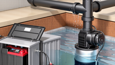
Mount the battery and charger above the anticipated flood level and protect them from condensation, splashing, and corrosive damp air. |
Confirm enclosure ratings, mounting height, drainage, cable entry protection, and separation from the sump pit. |
| Temperature range |
Battery capacity and charging performance change with temperature. Cold conditions generally reduce available capacity, while high temperatures can accelerate battery aging. |
Install the battery within the temperature range stated by the manufacturer and use temperature compensation when required by the charging system. |
Record the installation temperature range and compare it with the battery and charger specifications. |
| Routine inspection |
A backup system can fail because of a discharged battery, corroded terminals, a blocked discharge line, a failed charger, or a defective alarm. |
Inspect the system at least seasonally and after major storms; follow the manufacturer’s maintenance interval for battery testing and replacement. |
Test primary-power failure operation, pump activation, battery condition, charger status, alarms, and discharge flow. |